
CUSTOM ROBOTICS SOLUTION
Omnidirectional Mobile Robot Solution
Integrated chassis, navigation, safety and automatic charging.
1. Functions and Key Specifications
| Parameter | Specification |
|---|---|
| Overall Dimensions | 1050 × 850 × 900 mm |
| Navigation | Laser SLAM |
| Navigation Controller | SEER SRC-2000 |
| Maximum Travel Speed | 1.5 m/s |
| Battery Capacity | 100 Ah |
| Support Legs | 4 electric support legs |
| Automatic Charging | Up to 3 kW, 40–60 V |
| Manual Charging | Up to 0.8 kW |
Customized for Your Application
These specifications describe a reference configuration. Payload capacity, dimensions, navigation, battery capacity, and system interfaces can be tailored to your operating requirements.
Diagram 1: Overall dimensions of the equipment
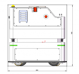
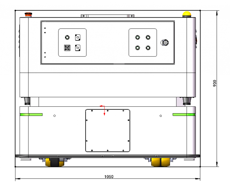
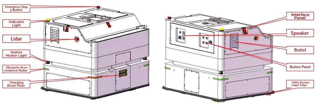
Diagram 2: Components of the equipment housing
2. Overall Exterior Design
1050 × 850 × 900 mm
Overall Dimensions · L × W × H
Durable Construction
Robust chassis designed for long-term industrial operation.
Lift-Ready Interfaces
Standardized mounting interfaces simplify future integration of lifting mechanisms.
Enhanced Stability
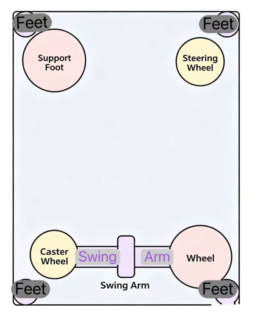
Four electric stabilizing legs provide additional support during stationary operation.
Integrated Safety
Emergency stop, warning lights, audible alerts, and safety bumpers.
| System | Main Components |
|---|---|
| Navigation & Sensing | LiDAR sensors, obstacle detection LiDAR |
| Controls & Interfaces | Control panel, interface panel, charging contacts |
| Safety & Alerts | Emergency stop, indicator lights, buzzer, safety bumpers |
Motion and Support Mechanism:
Dual steering-wheel drive enables omnidirectional movement. Four electric stabilizing legs deploy automatically during elevated operations for added stability. Brake-free drive wheels allow manual movement when powered off for emergency relocation and maintenance.
Diagram 3&4:
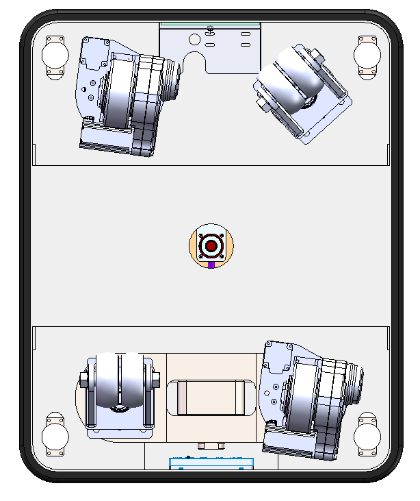
Diagram 5: Schematic Diagram of Chassis Support
3. Navigation System
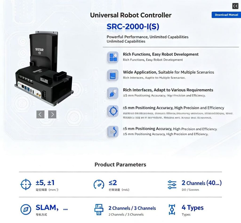
This system integrates the Seer Robotics SRC-2000 navigation controller. This model features mature technology, large market share, and a solid foundation in engineering applications. The system is equipped with two LiDAR units, arranged in an opposing configuration to achieve 360° omnidirectional environmental scanning and perception. The navigation adopts a laser SLAM technology solution, supporting real-time mapping, high-precision localization, and autonomous mobile operation. It can integrate ground codes to achieve composite positioning, with a repetitive stopping accuracy of ≤ ±10 mm.
Diagram 6: Navigation Controller Product Introduction
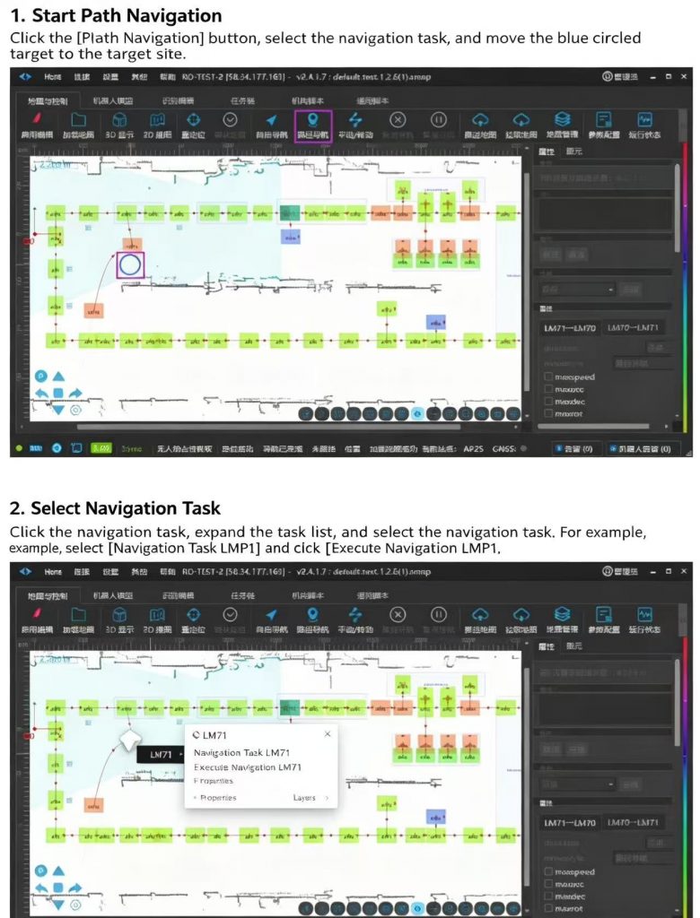
The navigation supporting software supports path planning and autonomous navigation based on a preset road network, and is equipped with automatic stopping and automatic obstacle avoidance safety processing capabilities. The maximum operating speed of the equipment can reach 1.5 m/s.
Diagram 7: Navigation Controller Product Introduction
4. Charging Station
The robot supports automatic and manual charging for flexible operation.
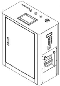
- Automatic Charging Station: Autonomous docking and charging with built-in protection and real-time status monitoring. Maximum output: 3 kW, voltage range: 40–60 V. Dimensions: 714 × 350 × 754 mm (L × W × H).
- Manual Charger: A dedicated 0.8 kW adapter supports charging during commissioning, maintenance, and special operating conditions.
- Protected Charging Contacts: Contacts retract behind a protective cover when not in use, reducing exposure to dust, moisture, foreign objects, and accidental contact.
Diagram 8: Physical Picture of the Manual Charger
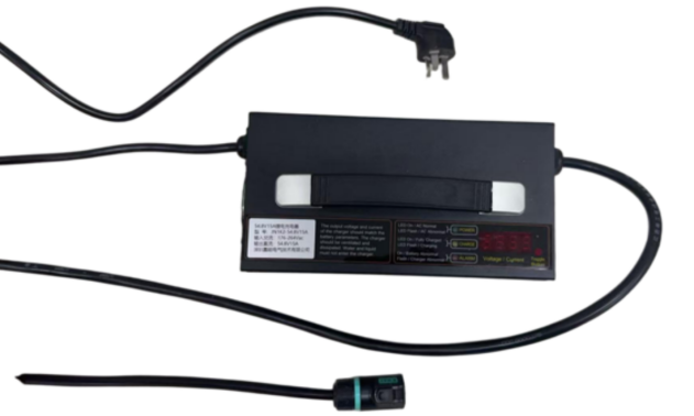
Diagram 9: Design Drawing of the Automatic Charging Station
5. Chassis Remote Control Handle
The robot can switch from automatic to manual mode, using a Logitech F710 wireless gamepad to control forward and backward movement, turning, and orientation adjustment. This supports commissioning, maintenance, on-site relocation, emergency control, and special operating conditions, improving operational flexibility and ease of maintenance.
Diagram 10: Physical Picture of the Chassis Remote Control Handle
6. Emergency Stop Remote Control Handle
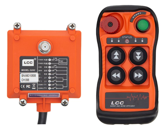
To ensure the safety of personnel and equipment during robot debugging, maintenance, and on-site operations, the system is equipped with a wireless emergency stop remote controller for remotely and emergently stopping the robot operation. When an abnormal situation occurs or there is a risk of personnel approaching, the operator can immediately cut off the action of the robot’s actuators through the remote controller, achieving rapid and safe shutdown of the complete machine.
The wireless emergency stop function covers all key actuators of the robot, including the mobile chassis, lifting mechanism, robotic arm, and other motion execution units, which can effectively reduce safety risks during equipment debugging and on-site operations, and improve the system’s safety protection capability.
The remote controller is equipped with physical function buttons, which can manually control the chassis electric support legs and lifting mechanism, facilitating emergency handling and on-site debugging of the lifting mechanism and chassis support legs, and improving equipment maintenance and debugging efficiency.
The wireless emergency stop system consists of a transmitter and a receiver. The receiver is installed inside the robot and integrated with the complete machine safety control system to achieve wireless safety signal reception and control.
Main technical parameters:
(1) Control method: Wireless remote control;
(2) Control objects: Mobile chassis, lifting mechanism, robotic arm, and other actuators;
(3) Additional functions: Supports manual control of electric support legs;
(4) Communication distance: Maximum control distance of 100 m (in open environment);
(5) Communication features: Stable signal, strong anti-interference capability, and good penetration performance.
Diagram 11: Wireless Emergency Stop Remote Controller (Left: Receiver; Right: Transmitter)
7. Network Module
An industrial CPE network module is integrated, supporting Wi-Fi access. It integrates switch functions and is equipped with 5 gigabit Ethernet ports, with intelligent routing and real-time data forwarding capabilities, meeting the requirements for multi-network-port usage. It supports multiple working modes including AP/Client/Repeater, with dual-radio multi-mode concurrent operation, flexible configuration, and adaptability to complex application scenarios.
It is designed with optimization for the pain points of wireless access in industrial sites, featuring strong wireless access compatibility and high connection reliability. The Client mode supports active fast roaming, seamless roaming among multiple APs, with an air interface handover time of ≤20 ms. It supports Profinet and Modbus industrial communication protocols, enabling dual-band dual-mode simultaneous operation. It is equipped with a built-in interference suppression module to improve communication stability in industrial noise environments. The hardware adopts wide-temperature and wide-voltage design, surge protection, and enhanced shock absorption design, making it suitable for harsh industrial working conditions. As a basic component unit of the Node Intelligent WiFi system, it can be used in conjunction with intelligent AP series equipment to improve the overall performance of the wireless communication system.